Extends ⇘ CIA405.CIA405BASE.
Input:
|
NETWORK |
USINT |
see CIA405.CIA405BASE |
|
ENABLE |
BOOL |
see CIA405.CIA405BASE |
|
TIMEOUT |
UDINT |
see CIA405.CIA405BASE |
|
DEVICE |
CIA405.DEVICE |
Addressed device; 0 means local device range: 0 … 127 initial: 0 |
|
CHANNEL |
USINT |
SDO channel number range: 1 … 128 initial: 1 |
|
INDEX |
WORD |
Object index range: 0000 … FFFF initial: 0 |
|
SUBINDEX |
BYTE |
Object subindex range: 00 … FF initial: 0 |
|
DATA |
POINTER TO BYTE |
Object data range: 00 00 00 00 … FF FF FF FF initial: 0 0 0 0 |
|
DATALENGTH |
USINT |
Length of valid data in bytes range: 1 … 4 |
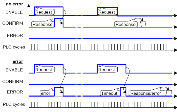
The figure above shows the timing diagram for CIA405.SDO_WRITE4. After all data is provided to the inputs, ENABLE is set to TRUE (1). The SDO will be sent, and when the CANopen software reports success to the function block, output CONFIRM will be changed to TRUE (2). The caller will see this and change ENABLE to FALSE (3), which in turn will cause output CONFIRM to change to FALSE (4).
- With a rising edge on input ENABLE, the function block will sample the inputs and initiate the transmission of the SDO specified in DATA and DATALENGTH to the recipient specified with DEVICE, INDEX and SUBINDEX. The value of DEVICE is limited to a range of 1 to 127. For access to the local object dictionary it is allowed to use the value 0 for DEVICE.
- With TRUE on input ENABLE, the function block is allowed to continue execution. If a result is reported on the call by lower level CANopen software, outputs CONFIRM, ERROR and ERRORINFO are set accordingly.
- With a falling edge on input ENABLE the function block will terminate. If the transmission did not finish yet, it will be aborted if possible. Outputs CONFIRM and ERROR will both be set to FALSE respectively "no error".
- With a FALSE on input ENABLE, the function block will return immediately and not take any action.
- For behavior of ENABLE, CONFIRM and ERROR see chapter ⇘ “Control mechanism”.
- For inputs NETWORK and TIMEOUT see chapter ⇘ Additional parameters .
- The input DATA defined as ARRAY[1..4] OF BYTE contains the least significant data byte at the lowest array index. Example: the value 16#01020304 (hexadecimal) is assigned as ARRAY[1..4] OF BYTE := 04, 03, 02, 01
The result of a writing operation is reported (immediately after the writing call or afterwards) in outputs CONFIRM, ERROR and ERRORINFO with a rising edge on either CONFIRM or ERROR. In case of ERROR is equal to 1 (other error), ERRORINFO will give more specified information on the cause. This is especially true for the occurrence of an SDO Abort. Then ERRORINFO contains the Abort code.
It cannot be assumed in general that this function can synchronously complete; rather, it should be possible to have this function continue to be executed while the call to CIA405.SDO_WRITE4 returns and the PLC program is continued. Therefore, the result of a call may be available only several cycles after a rising edge has been applied to ENABLE.